Calculation formula of steel structure
- 20 Dec 2019
- steel structure
1.Calculation formula of strength and stability of steel structure members
Strength and stability calculation table
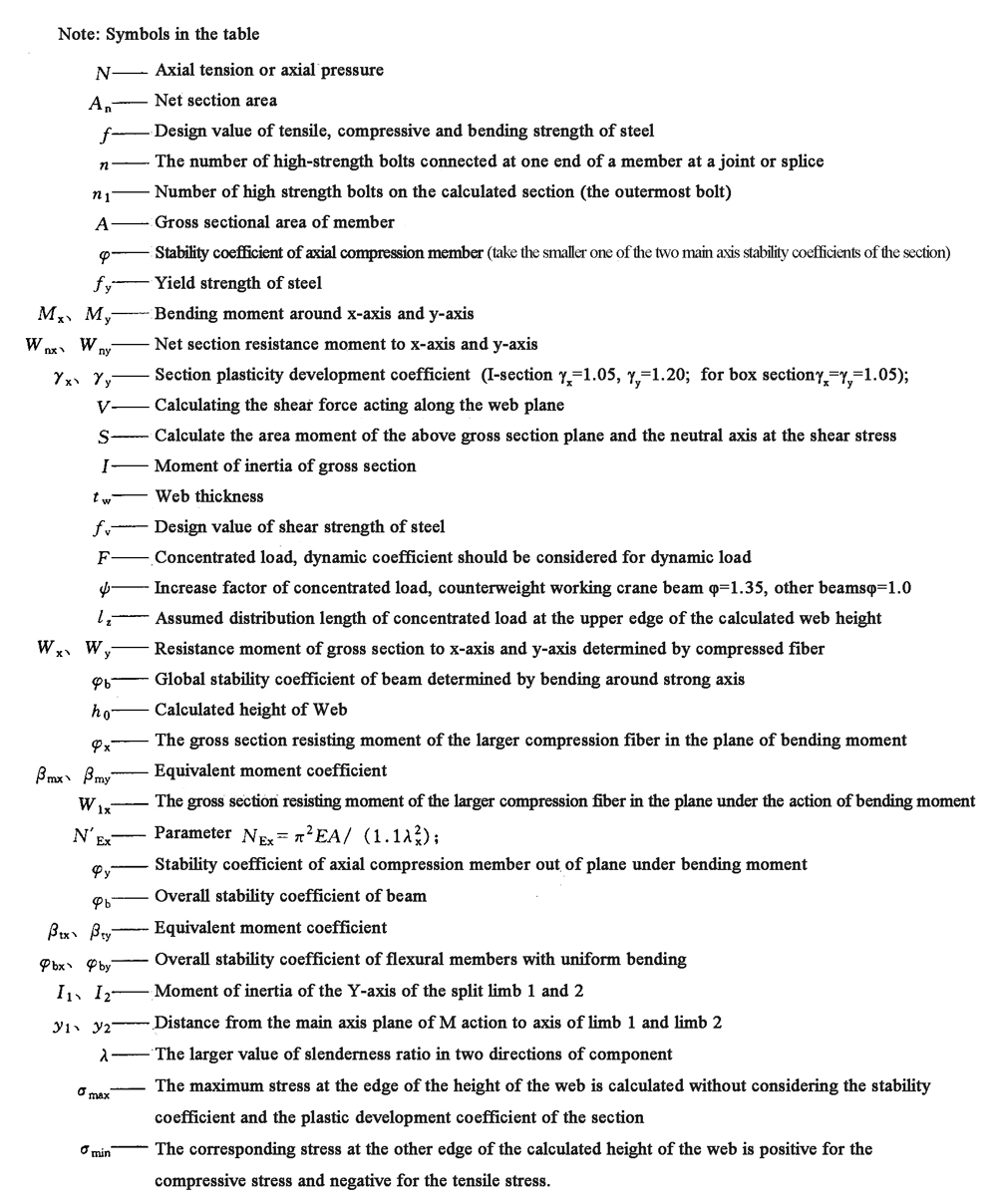
| No. | Component category | Content of calculation | Calculation formula | Notes |
|---|---|---|---|---|
| 1. | Axial tension members | Strengt |
|
|
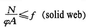
| 2. | axially compression members | strength | Concentric tension member | |
| Stabilization force |
|
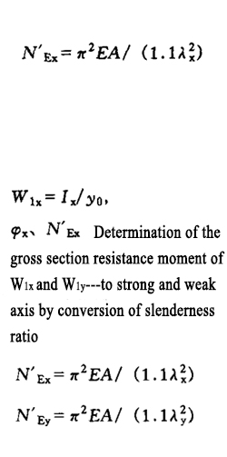
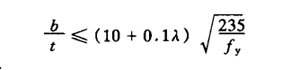
The slenderness ratio of lattice members to the required axis shall be the converted slenderness ratio | ||
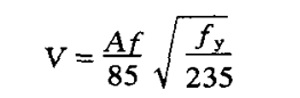
| Shear force | It shall be able to bear the shear force calculated by the following formula:
|
Lattice member,The shear force V shall be shared by the batten surface bearing the shear force | ||
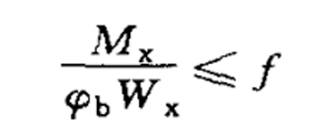
| 3. | Flexural member | Bending strength(Solid web member in main plane) |
|
|
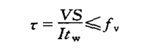
| Shear strength(Solid web member in main plane) |
|
|||
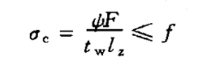
| Local bearing strength(Upper edge of calculated height of abdomen) | When the upper flange of the beam is subjected to a concentrated load acting along the plane of the web, and no supporting stiffener is set at the load place:
|
|||
| Overall stability | (1)Members bent in the principal plane of maximum stiffness:
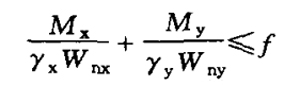
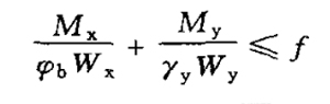
(2)I-shaped or H-shaped section members bent in two main planes:
|
|||
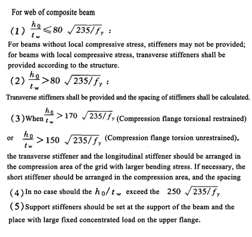
| Local stability |
|
|||
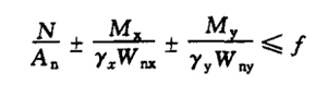
| 4. | Stretch bending member | Strength(Bending moment acting in the main plane) | (1)Bear the experienced load or indirectly bear the dynamic load:
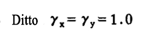
(2)Tension bending and compression bending members requiring fatigue calculation:
|
|
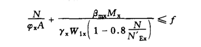
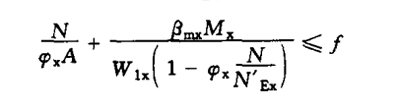
| stability | (1)Solid web compression bending members: bending moment acting in the plane of symmetric axis(X axis), Stability in plane under bending moment
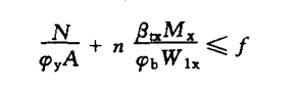
Stability out of plane under bending moment
(2)Lattice compression bending member (a)Bending moment around virtual axis (x-axis): Stability in plane under bending moment:
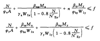
Global stability in the plane of bending moment, it is unnecessary to calculate the overall stability outside the plane of bending moment. However, the stability of the split leg shall be calculated, and the axial force of the split leg shall be calculated according to the chord of the truss. (b)Bending moment around solid axis: Global stability in the plane of bending moment: The calculation is the same as that of solid web compression bending members Global stability out of plane under bending moment: The calculation is the same as that of the solid web compression bending member, and the slenderness ratio is the converted slenderness ratio, Φb is 1.0 (3)Biaxial symmetrical solid web I-section and box section compression bending members: bending moment acts in two main planes
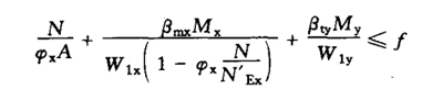
(4)Two leg lattice compression bending members: bending moment acting in two main planes (a)Calculated as a whole
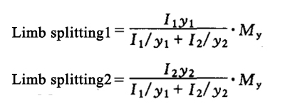
(b)Calculation by limb Under the action of N and Mx, the split limb is used as truss chord to calculate its axial force, My is distributed to the two split limbs according to calculation, and then the stability of the split limb is calculated according to the solid web compression bending member
|
|
||
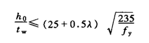
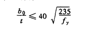
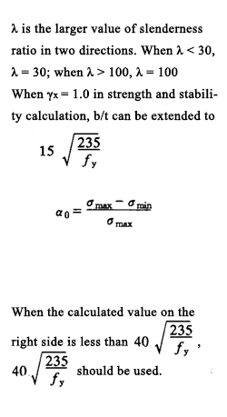
| 5. | Compression member | Local stability | (1) axial compression member: the ratio between the free extension width b of flange plate and its thickness t shall conform to
(2) bending members shall conform to
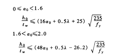
(3) I-section and H-section axial compression members: shall conform to
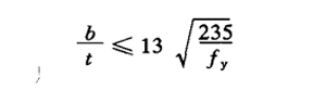
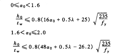
(4) I-section and H-section axial compression bending members: shall conform to
(5) the ratio of width b of compression flange of box section between two webs and its thickness t shall conform to
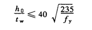
(6)the ratio of the calculated height h of the web to the thickness t of the box section axial compression member shall conform to
(7) the box section bending members shall conform to
(8) for T-section compression members, the ratio of web height to its thickness shall not exceed: (a) axial compression members and compression bending members whose bending moment makes the free edge of the web tensioned
(9)The ratio of outer diameter to wall thickness of compression members with circular pipe section shall not exceed 100(235/fy) |
|
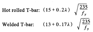 (b) compression bending member with bending moment to compress the free edge of Web
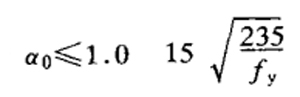
2. Calculation formula of steel structure connection
Connection calculation formula
| No. | Connection type | Content of calculation | Calculation formula | Notes |
|---|---|---|---|---|
| 1 | Weld connection | Butt weld | (1) in butt joints and T-joints, butt welds perpendicular to the axial tension or axial pressure or combined butt and fillet welds
|
|
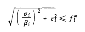
| Right angle fillet weld | (1) under the action of tension, pressure or shear force passing through the weld core: correct weld (when the force is perpendicular to the weld length direction)
Side fillet weld (when the force is parallel to the weld length direction)
|
|||
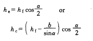
| Bevel fillet weld | Calculated according to the formula of right angle fillet weld, but β = 1.0, Calculated thickness:
|
α is the angle between two weld legs | ||
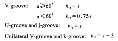
| Butt weld with partial penetration | Calculated according to the formula of right angle fillet weld and under the pressure perpendicular to the weld length direction, β = 1.22 is taken, and β = 1.0 is taken for other stress conditions. Effective thickness:
|
S is the shortest distance from the groove root to the weld surface (without considering reinforcement) α is V-groove angle |
||
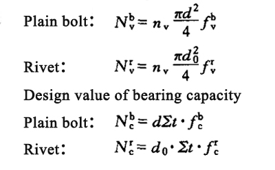
| 2 | Bolt connection and rivet connection | Shear connection of ordinary bolts, anchor bolts and rivets | The design value of bearing capacity of each ordinary bolt or rivet shall be the lesser of the design value of shear and bearing capacity: Design value of shear capacity:
|
|
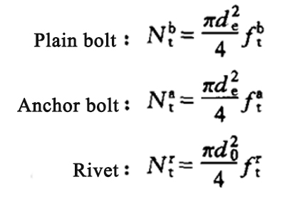
| Axial tension connection of common bolt, anchor bolt and rivet rod | Design value of bearing capacity of each ordinary bolt, anchor bolt or rivet:
|
|||
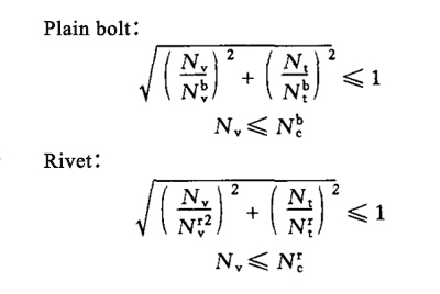
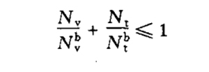
| Common bolts and rivets bear both shear and axial tension |
|
|||
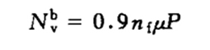
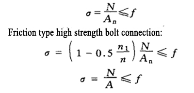
| Friction type high strength bolt shear connection | Design value of bearing capacity of each friction type high strength bolt
|
|||
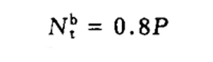
| Friction type high strength bolt rod axial tension connection | Design value of bearing capacity of each friction type high strength bolt
|
|||
| The friction type high strength bolt connection bears the shear force between the friction surfaces and the pull force in the direction of the rod axis at the same time | Design value of shear capacity of each friction type high strength bolt
|
|||
| Pressure bearing high strength bolt shear connection | The calculation formula is the same as that of ordinary bolt | |||
| Pressure bearing high strength bolt compression connection | The calculation method of bearing capacity design value of each bearing type high strength bolt is the same as that of common bolt | |||
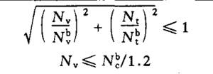
| Bearing type high strength bolt bears both shear force and axial tension |
|