Single-storey portal steel structure workshop
- 21 Oct 2019
- steel structure
Portal steel structure:
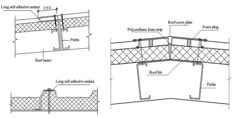
H-shaped steel portal frame is the main load-bearing framework,cold-formed thin-walled is used as steel purlin and wall beam, and profiled metal plate is the roof and wall.
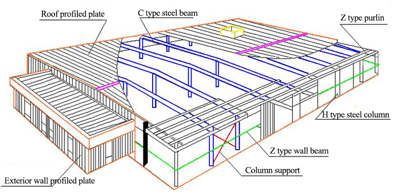
Features: A steel structure with rigid joints is composed of straight-line members (beams and columns).
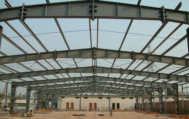
The main contents of steel structure design drawings are as follows:
1. Drawing catalogue
2. Design instructions
3. Architectural drawings (horizontal, vertical and sectional drawings)
4. Structure diagram:
4.1 Layout of anchor bolts
4.2 Structural Layout (Roof Layout, Column Layout, Crane Beam Layout, etc.)
4.3 Portal Frame Diagram
4.4 Node Details
4.5 component diagram
5. Construction drawings:
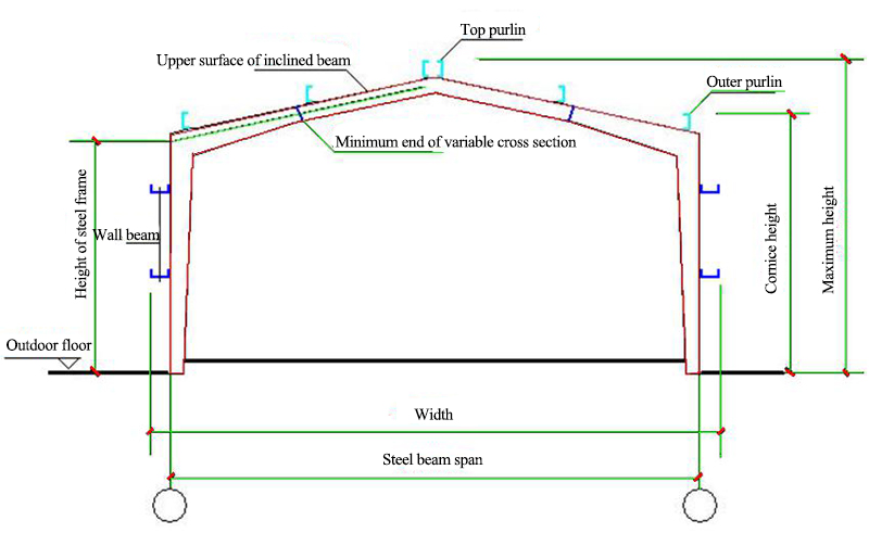
5.1 The span of portal steel frame - the distance between the axes of transverse steel frame columns;
5.2 Height of portal steel frame - the height from outdoor terrace to the intersection of column axis and inclined beam axis. The axis of inclined beam is the axis parallel to the upper surface of inclined beam through the minimum end center of variable section beam section;
5.3 The orientation axis of the industrial building side column takes the outer skin of the column.
5.4 The eaves height of portal steel frame houses - the height from outdoor flat to the upper edge of purlin outside the roof;
5.5 The maximum height of a portal steel frame building - the height from the outdoor floor to the purlin upper edge of the roof top;
5.6 Width of Portal Steel Frame House - Distance between the Skin of Side Wall Beam.
Drawing explanation:
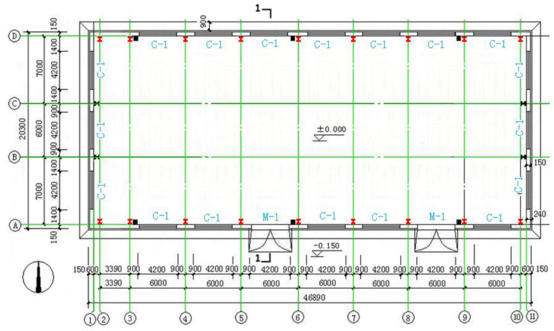
1.Plan
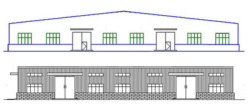
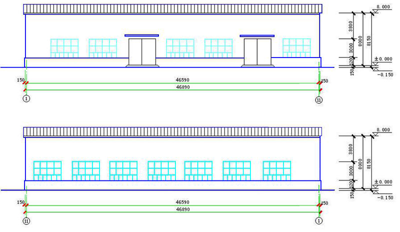
2. Elevation

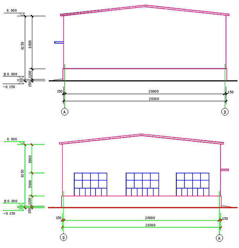
3. Section plan
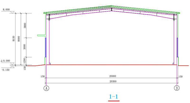
4. Architectural plan:
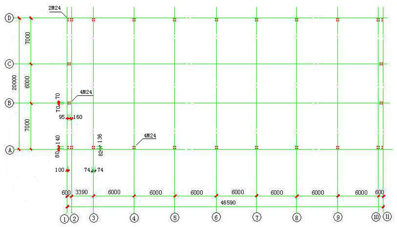
4.1 Base bolt layout plan: The location of each column should be combined with the basic plan.
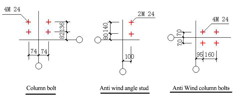
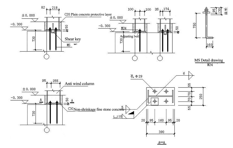
4.2 Connection Joints of Column Foot of Rigid Frame:
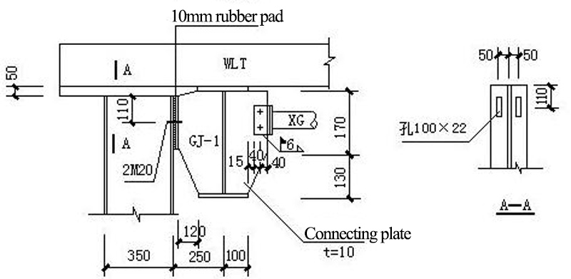
4.3 GJ-1(Portal frame)
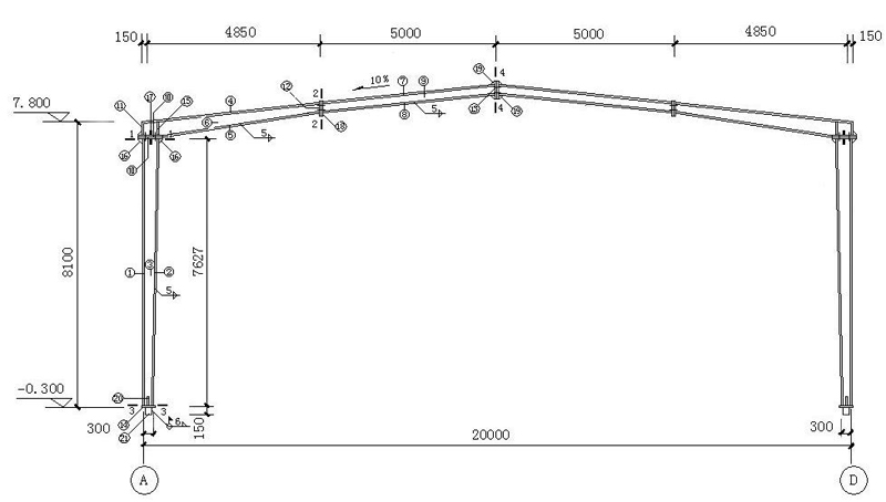
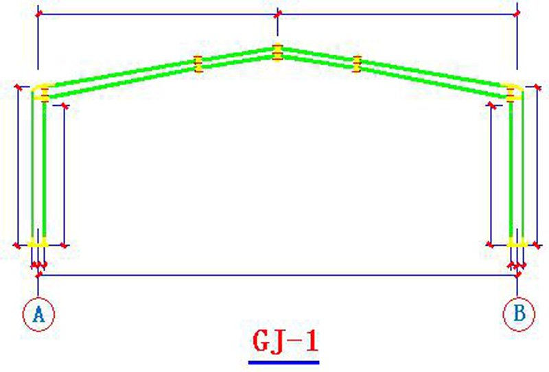
4.4 GJ-1connection joints
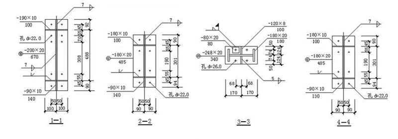
The portal frame is composed of solid web steel columns with variable cross-section and solid web steel beams with variable cross-section.;
Span20m,Cornice height7.8m,Slope of building1:10;
Section of steel column:(300~488) mm×180mm ×8 mm×10mm;
Section of steel column:(301~464) mm×180mm ×8 mm×10mm。
5. Structural Plane Layout: Position of Rigid Frame, Wind Column and Rigid Frame Support
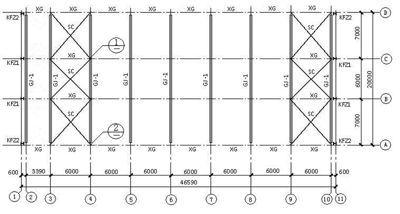
GJ-1: rigid frame; XG:Tie bar; SC:Brace (horizontal direction)); KFZ1:1 wind resistant column; KFZ2:2 wind resistant column
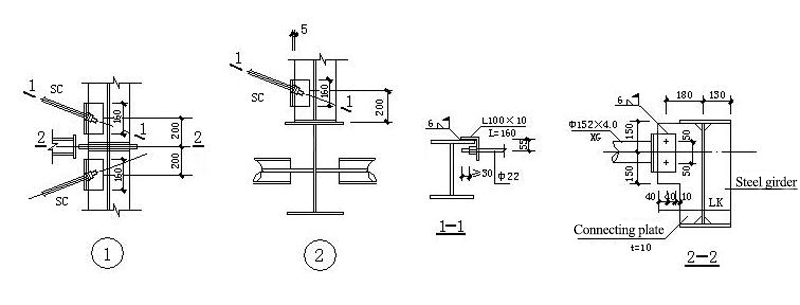
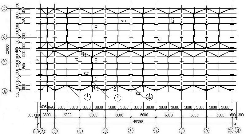
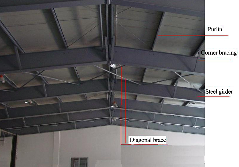
6. Plane Layout of Roof Purlins, Tendons and Corners
6.1 Roof Connection Node
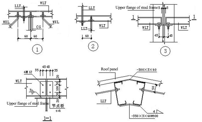
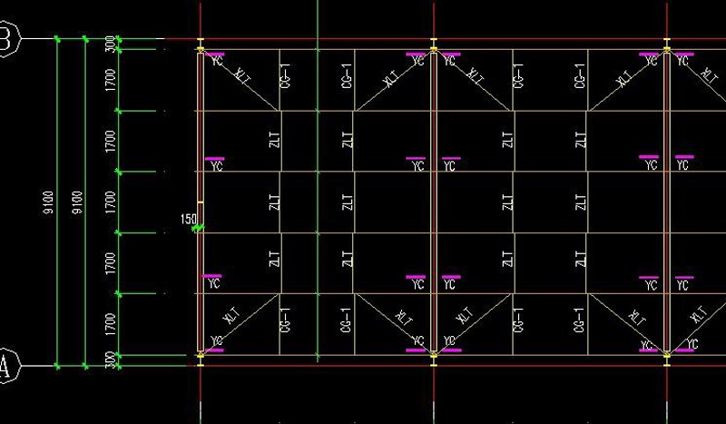
WLT: roof purlin; LLT:straight brace; WXT:batter brace; CG:Poles (arranged at WLT); YC:Corner bracing
Corner bracing:Supporting rods between beams and purlins, columns and purlins。The supporting rod on the wall is called the wall corner support, and the supporting rod on the roof is called the roof corner support.The angle between the knee brace and the web of the steel frame should not be greater than 45 degrees.
Function: In order to ensure the out-of-plane stability of components and reduce the out-of-plane calculation length of components.
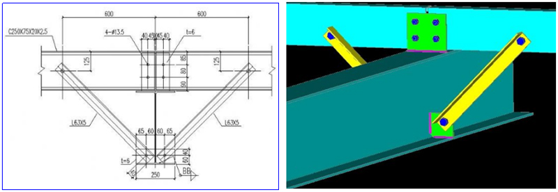
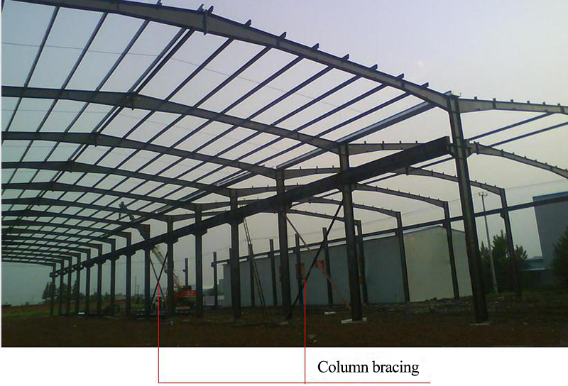
7. Support layout
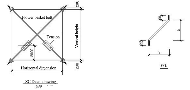
7.1 ZC:column bracing(vertical direction)

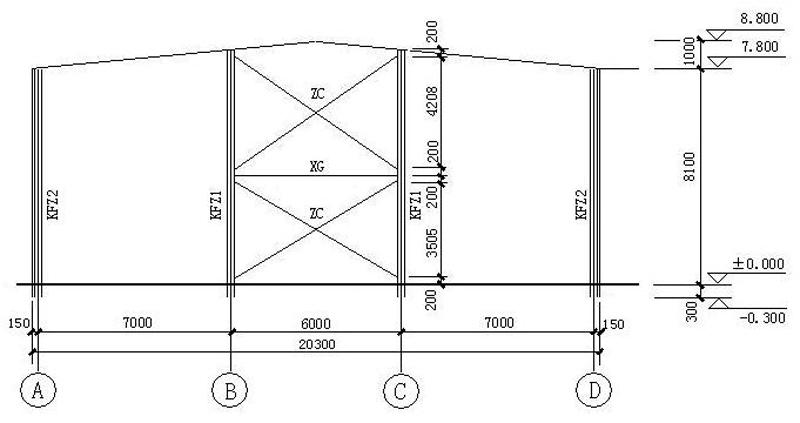
7.2 Detailed drawings of supporting joints
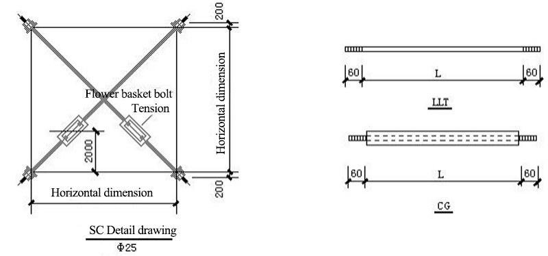
8. Wall and Beam Layout
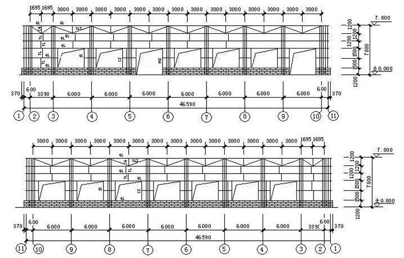
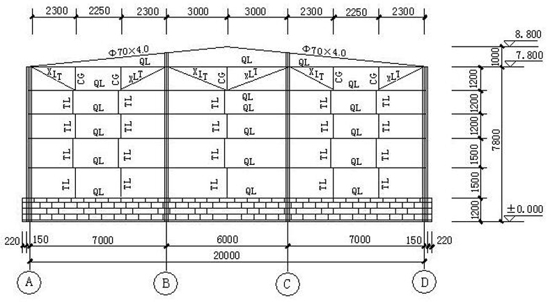
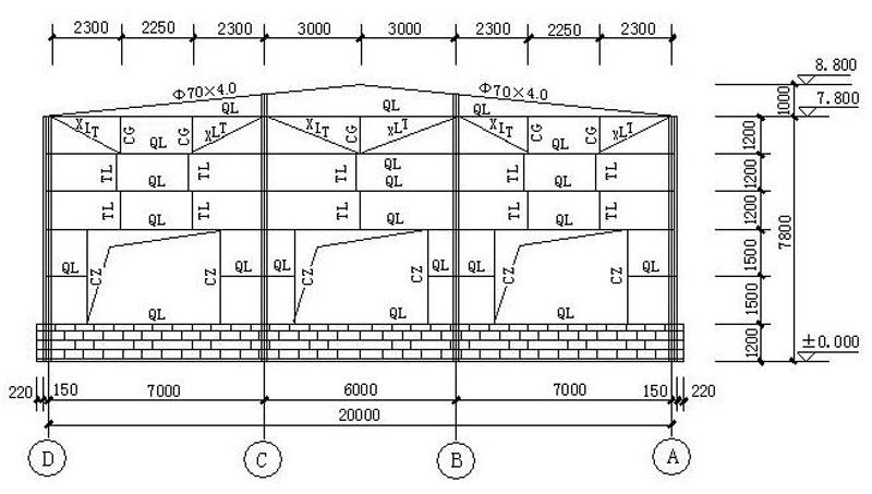
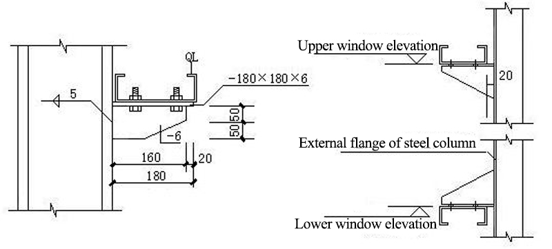
9. Connection joints
9.1 Installation of Wall Beam and Rigid Frame Column
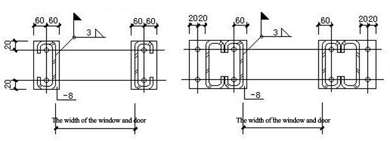
9.2 Doors and windows nodes
9.3 Wind Column Connection Joints
9.4 Wall Beam and Wall Board Connection
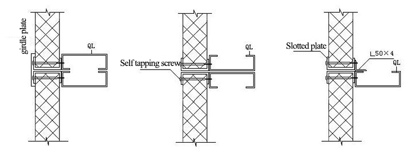
9.5 Wallboard connections
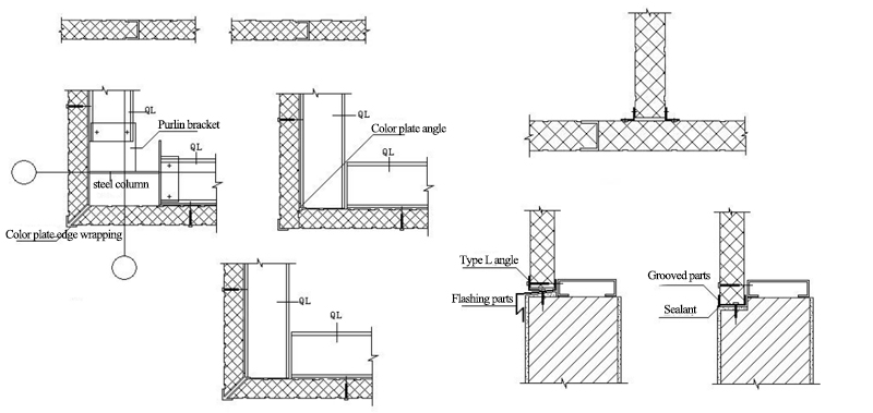
9.6 Gable wall and Parapet node
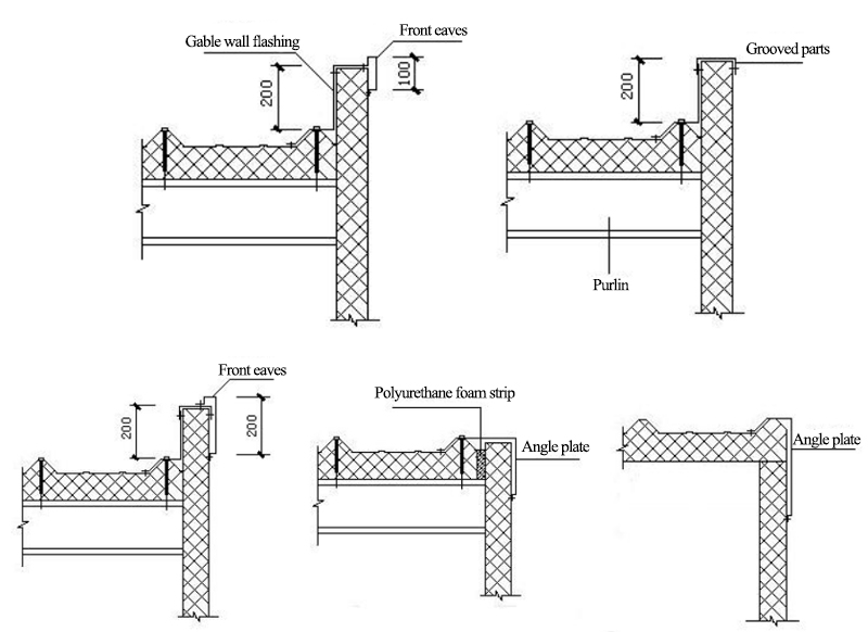
9.7 Roof panel joints
