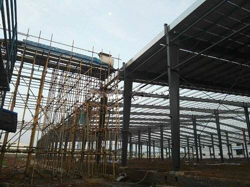
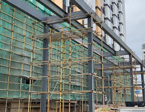
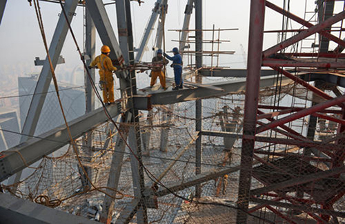
Steel structure installation safety platform
- 09 May 2020
- steel structure

Design scheme of steel structure safe operation platform
1. Operating platform design parameters
The full hall fastener type steel pipe scaffold support frame will use steel pipes, and the stacking load and construction load shall not exceed the following values (centralized stacking shall be avoided): the maximum stacking load of materials is 0.8kn/m2 (stacking load of electric welding machine), and the construction live load is 2.0kn/m2.
2. Design of safe operation platform for full hall fastener type steel tube scaffold
2.1 Combined layout of fastener type steel pipe scaffold
In order to meet the requirements of the full scaffold erected in the construction of steel structure, the poles must be butted, and the overlapping and lengthening are not allowed.
2.2 pole setting of fastener type steel pipe scaffold
(1) The length of the vertical pole extending out of the center line of the top horizontal pole to the supporting point shall not exceed 0.5m. The height of full platform erection shall not exceed 30m.
(2) The base or cushion block should be set at the bottom of each vertical pole.
(3) The scaffolds must be equipped with vertical and horizontal bottom sweepers. The longitudinal bottom horizontal tube shall be fixed on the vertical tube no more than 200 mm from the bottom of the steel tube with right angle fastener. The transverse sweeping bar shall be fixed on the vertical bar next to the longitudinal sweeping bar with right angle fastener.
(4) When the foundation of scaffold pole is not at the same height, the vertical bottom bar at the high place must be extended for two spans to the low place and fixed with the pole, and the height difference shall not be greater than 1 m. The distance between the axis of the pole above the side slope and the side slope shall not be less than 500mm.
2.3 Setting of reinforcing bar and shear support of fastener type steel tube scaffold
(1) The erection height of full scaffold shall not exceed 36m; the construction layer of full scaffold shall not exceed 1 layer.
(2) Horizontal reinforcing bar: the step distance of the vertical and horizontal horizontal tie rods is 1.5m. When the floor height is 8m-20m, a horizontal tie rod shall be added between the two horizontal tie rods at the top step. A fixed joint shall be set between the horizontal tie rod and the building structure according to the horizontal spacing of 6-9M and the vertical spacing of 2-3m. This project adopts the form of holding (hooping) column to strengthen the overall anti overturning ability of the platform.
(3) Cross bracing: the scaffold shall be provided with continuous vertical cross bracing from the bottom to the top every 6m to 8m in the vertical and horizontal directions around the outside and inside the scaffold. When the erection height of the frame is less than 8m, continuous horizontal cross bridging shall be set at the top of the frame; when the erection height of the frame is 8m or more, continuous horizontal cross bridging shall be set at the bottom of the frame and at the vertical interval of not more than 8m. Horizontal diagonal bracing should be set in the intersection plane of vertical diagonal bracing. The width of the bridging shall be 6m-8m. The cross bridging shall be fixed on the horizontal bar or vertical bar intersecting with it by the rotating fastener, and the distance from the center line of the rotating fastener to the main node shall not be greater than 150 mm.
(4) Wall connecting parts: the height width ratio of the full scaffold should not be greater than 3. When the height width ratio is greater than 2, the wall connecting parts and the building structure should be set at the outer and inner horizontal intervals of 6m-9m and vertical intervals of 4m-6m. When the wall connecting parts cannot be set, the steel wire rope should be set for tensioning and fixation.
(5) Construction stairs: ladders shall be set for the full scaffold, and the step spacing of ladders shall not be more than 300 mm.
The top support of all supports shall be adjustable main ridge, and the bottom support base of upright shall be supported by scaffold. The main stud should not exceed 200mm.
2.4 Setting of platform plate, guardrail and pocket net
(1) The platform plate is made of 18mm plywood, and the bottom of the plate is laid on 80 cross braces, which are placed on the jacking pipe. Snap out the position line and horizontal control elevation line of the platform, adjust the scaffold according to the design elevation (adjust the elevation of the adjustable jacking, adjust it to the predetermined height, and then place the wooden brace on the supporting plate of the adjustable jacking).
(2) The construction of protective guardrail has been completed during the erection of high formwork, which can meet the requirements of safe operation platform.
(3) Before installing the platform plate, a layer of bottom net shall be set 1.5m below the platform plate.The bottom net must be reliably tied with the surrounding steel pipes to ensure the stability and safe use performance of the bottom net, and the bottom net shall be correctly selected and used according to the relevant requirements.
2.5.1 Lightning protection device
The erected steel pipe scaffold shall be equipped with lightning protection device in thunderstorm season, including lightning arrester, grounding electrode and grounding wire.
(1) The top of scaffold is higher than 2m, and each external corner is provided with lightning rod.
(2) The grounding wire of the grounding device shall be three conductors, which shall be electrically connected with the grounding body at different points. The vertical grounding body shall be 50 × 5 angle steel, φ 48 steel pipe or φ 22 round steel, with a length of 2.2m. The threaded steel shall not be used, and the grounding resistance shall not be greater than 4 Ω.
2.5.2 Lightning arrester
The lightning arrester is the lightning rod, which can be made of galvanized pipe with a diameter of 25-32mm and a wall thickness of not less than 3mm or galvanized steel bar with a diameter of not less than 12mm. It is set on the scaffold pole at the four corners of the house, with a height of not less than 1m, and the top horizontal pole shall be connected to form a lightning protection network. When installing the lightning rod on the vertical transport frame, the middle vertical rod on one side shall be connected to the top by not less than 2 meters, the lower end of the vertical rod shall be provided with grounding wire, and the shell of the winch shall be grounded.
2.5.3 The grounding wire shall be made of steel as much as possible
The vertical grounding electrode can be made of steel pipe with a length of 1.5-2 meters, a diameter of 25-30 mm, a wall thickness of not less than 2.5 mm, and a round steel or 50 × 5 angle steel with a diameter of not less than 20 mm. For horizontal grounding electrode, round steel with a length of not less than 3m and a diameter of 8-14mm or flat steel with a thickness of not less than 4mm and a width of 25-40mm can be selected. In addition, metal pipes, metal piles, drilling pipes, water suction pipes buried in the ground and metal structures with reliable connection with the earth can also be used as grounding electrodes. One grounding electrode shall be set within 50m according to the continuous length of the scaffold, and the transition resistance of the scaffold within the farthest point from the grounding electrode shall not exceed 10 ohm. The ground resistance shall not exceed 20 ohms. The grounding electrode shall be buried in the highest point of the ground and not less than 50cm below the ground, and the new fill shall be compacted during the embedding. The ground wire shall not be buried in the soil layer near the steam pipeline or chimney air duct which is often hand heated, in the brick cinder or sand above the groundwater level, and in the particularly dry soil layer.
2.5.4 Ground wire is downlead
Aluminum conductor with a section of not less than 16 mm or copper conductor with a section of not less than 12 mm can be used.
In order to save non-ferrous metals, round steel with diameter no less than 8mm or flat steel with thickness no less than 4mm can be used under the premise of reliable connection. The connection of the grounding wire shall be absolutely reliable. During the connection, the paint and oxide layer on the contact surface shall be removed to expose the metallic luster, and neutral Vaseline shall be applied. Welding is the best way to connect the grounding wire and the grounding electrode. The length of the welding point shall be more than 6 times of the diameter of the grounding wire or more than 2 times of the width of the flat steel. If it is connected by bolts, the contact surface shall not be less than 4 times of the sectional area of the grounding wire, and the diameter of the splicing bolt shall not be less than 9 mm.

Installation and removal of safe operation platform
1. Erection and removal
1.1 The erection and demolition personnel must be in good condition with certificates. After the quality and safety technical disclosure, they can accurately grasp the characteristics and methods of the erection and demolition of the unloading platform of the project.
1.2 During erection and demolition, full-time safety officer shall be appointed to direct and guard, warning area shall be demarcated, warning signs shall be set, and non erection and demolition personnel shall not enter the construction area.
1.3 Erection process of support frame:
Place the base cushion block of the vertical pole → place the longitudinal sweeping pole → column → transverse sweeping pole → large transverse pole → small transverse pole → diagonal bracing and wall connecting pieces → surrounding railings of platform three → bottom net → pave the platform board and toe board of the architrave wood and plywood.
1.4 Installation inspection: Before installation, check the physical condition of operators, protective equipment, safety mechanical equipment and installation environment, etc.
1.5 Removal of operation platform:
Before dismantling, safety technical disclosure must be done well, safety warning tape shall be set in the dismantling area. Non construction personnel shall not enter the area, and full-time safety officers and constructors on site shall command and supervise the whole process.
1.5.1 The removal shall be carried out according to the sequence of first removal of the later installed components and later removal of the first installed components. The removal must be carried out layer by layer from the top to the bottom. It is strictly prohibited to work up and down at the same time. Workers must stand on the scaffold board temporarily set for disassembly, and use safety protection articles as required. After the demolition work, the site shall be cleaned and painted for maintenance.
The disassembled steel pipes and formworks shall be stacked together as a whole, and the tower crane shall be used to bind and lift them to the ground. The disassembled fasteners shall be piled up according to regulations, and the disassembled materials shall not be thrown down during the disassembly process.
2. Inspection and acceptance of operation platform
2.1 The operation platform shall be erected in strict accordance with this plan. Steel pipes and safety nets must be provided with product certificates.
2.2 The project department shall organize 100% self inspection and acceptance of the unloading platform, which can be put into use only after passing the acceptance of the supervision unit and signing for confirmation.
2.3 During the use of the platform, a special person shall be responsible for regular maintenance and inspection at any time. If any problem is found, a warning sign shall be put up in time and reported to the superior for handling. The platform can be reused only after the problem is checked again and no problem is found.
2.4 No one or any department is allowed to change the unloading platform without permission.If the change is necessary due to the actual situation, it can only be carried out with the consent of the approval department of this plan.
